
Introduction
Network emulation and simulation frameworks are essential for designing, developing, and analyzing the creation of communications systems. The differences between network emulation and simulation are described in the post Network Emulation vs Simulation.
Graphical presentations of data are powerful instruments for the communication of research results. Graphical outputs produced using network emulation and simulation tools are essential to system development, testing, and customer demonstrations.
Here we present the creation of a custom EMANE viewer, eView, that supplements the EMANE network emulation framework by providing real-time graphical output as spectrum and waterfall views of EMANE network emulation over-the-air (OTA) activities and events. While eView was designed for use within the EMANE environment, it may also be driven with stream results from other applications which benefit from real-time spectrum and waterfall views.
Time-Frequency Analysis
The design of digital communications systems requires the performance and interpretation of time-frequency signal analysis. In practical communications applications, signals are non-stationary and their frequency-domain representation (their spectrum) changes over time.
To create and analyze communications systems, communications engineers utilize time-frequency techniques over pure frequency-domain techniques, which is a time-domain representations of a signal. Having an overview of all signals across a portion of the spectrum allows an engineer to quickly and easily determine whether there are any strong or weak signals at various frequencies. Time-Frequency analysis is particularly important when working with adaptive frequency agile based communications and custom waveforms.
What communications engineers typically need to know:
- What frequency components are present in my signal?
- How do I increase the time or frequency resolution for inspection and analysis of my signal?
- How can I sharpen the spectrum of a component or extract a particular mode?
- How do I measure power in a time-frequency representation?
- How do I visualize the time-frequency information of my signal?
- How do I find intermittent interference within the frequency content of the signal of interest?
- What is my signal’s spectral content, the power distribution as a function of frequency?
- What is the time history of my signal?
- How does the system respond in the presence of noise, interference, or jamming?
Time-frequency analysis by communications engineers is typically visualized using the standard display types described in the following paragraphs.
Spectrum Analyzer View
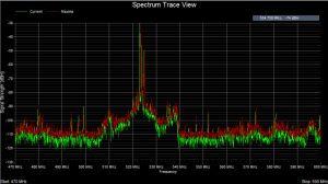 Typical communications systems design utilizes special test equipment for measuring time-frequency properties of a system. This will almost certainly include a standalone hardware or software based spectrum analyzer. A spectrum analyzer measures the magnitude of an input signal versus frequency within the full frequency range of the instrument. The primary use is to measure the power of the spectrum of known signals of interest, and unknown signals such as noise or jamming signals.
The input signal that a spectrum analyzer measures is electrical. A spectrum analyzer typically provides an FFT frequency representation of a real-time analog electrical signal. The frequency components for the signal and their magnitude are displayed, and the persistence (or sometimes the color) of the display indicates the time duration of each frequency component associated with the sweep rate of the spectrum analyzer.
Waterfall View
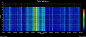 While a pure spectrum analysis provides a time-frequency display of a input signal, it does not capture the time history of this information for analysis. The historic view of the time-frequency relationship of a signal is typically captured and displayed using a waterfall view, often referred to as a waterfall plot with heat map, or density map. Waterfall graphs is a data visualization technique, normally used for understanding how an initial value is affected by a series of intermediate positive or negative values. A heat map is a graphical representation of data where the individual values are represented as a matrix of colors. A waterfall view is a graphical representation of the signals across a frequency range, generally color-coded to indicate signal amplitude or strength, displayed over time.
Many real time spectrum analyzers are now commonly equipped with persistent displays as a waterfall display. This display method adds a measure of significance—usually based upon a color pattern corresponding to the amplitude at a single frequency over time—to signal energy as specific frequencies that occur over time.
In a waterfall view, frequency signals can be very narrow (representing only a few tens of Hz of spectrum), but it could easily cover a much larger frequency range when in a “zoomed out” state. Waterfall views typically use black and dark blue colors to indicate background noise, and bright white to represent a very strong signal.
EMANE Network Emulation
 For real-time network emulation, we utilize the Extended Mobile Ad-hoc Network Emulator (EMANE) framework. EMANE is a next-generation framework for real-time modeling of mobile network systems. For discrete event network simulation, we utilize OPNET Modeler. The EMANE framework has a focus on real-time modeling of link and physical layer connectivity so that network protocol and application software can be experimentally subjected to the same conditions that are expected to occur in real-world mobile, wireless network systems. The EMANE architecture provides for Network Emulation Modules (NEMs) that can be associated with computer system (real or virtualized) network stacks as interfaces. The EMANE framework further provides an event-driven control bus and logging facilities.
EMANE provides emulation activity and results in the form of standard text log files with a user selected log verbosity level. Results may also be viewed by querying and displayed (in text format) by accessing the information stored in EMANE components as tables and values by way of the EMANE shell (emanesh). The OpenTestPoint data collection framework supported by EMANE provides a mechanism for mining various information from the running emulation for presentation, but this is also text based rather than graphical information.
EMANE graphical output is currently limited to a 2D network topology and link quality viewer showing multi-hop neighbor communications nodes (when olsrd is used for routing), along with GPS information (when using the location based path loss propagation model and gpsd) for each test node.
While expensive network simulation packages such as OPNET contain 2D line graphs for test results, real-time spectrum and waterfall views do not currently exist using the EMANE framework nor the OPNET package. This makes the eView application a bit unique in its functionality.
EMANE Over-The-Air (OTA) Control Bus
To emulate the RF spectrum for emulated nodes, EMANE provides a control bus for over-the-air (OTA) network traffic. The EMANE framework utilizes a control bus defaulting to IP multi-cast LAN (e.g. Gbps Ethernet) to act as the OTA interface between radio nodes. This logical OTA control bus is typically created external to EMANE proper as a Linux bridge, which is a named instance with an assigned IP address.
All EMANE NEMs monitor and receive the OTA transmission from other nodes on this OTA network interface, but based on the the receive sensitivity of the node compared to the transmit signal level, path-loss, and antenna gains, the Physical (PHY) layer of the EMANE stack may drop the packet. Depending upon the EMANE model used, some models provide a probability of reception (POR) curve, comprised of a series of SINR values along with their corresponding POR, to define and customize the link drop characteristics relative to path-loss. The EMANE Physical Layer Model describes the propagation models, the receive power calculation and components, and the criteria for packet drops and receptions.
Network Simulation and Emulation Visualization Tools
While the EMANE and OPNET provide industry leading environments for network emulation or simulation, it if often necessary to create visualization tools to allow for understanding the results of the network simulation or emulation for design, development, and customer presentations. As a result of this need, we have developed various visualization tools to allow for visually analyzing the performance of network simulation and emulation as described as Network Visualizer and Embedded Visualizer.
While these tools demonstrate the historic need to develop custom visualization tools to support real-time embedded communications systems development, or network simulation/emulation, neither of these two custom tools support real-time spectrum and waterfall views within the EMANE network emulation framework.
Custom EMANE Viewer eView
To provide time-frequency visualization for the EMANE network emulation environment, we have created a visualization tool, eView, that combines a spectral plot along with a waterfall plot. eView monitors the real-time traffic on the EMANE OTA control bus, representing RF transmissions into the shared RF medium, decoding and displaying this content as real-time spectrum/waterfall views.
eView Transmit Duration Display Persistence
The EMANE PHY header includes a transmit time and a transmit duration for each network packet. A single transmission can consist of one or more frequency segments. An EMANE radio model will typically include a TimeStampControlMessage when sending a downstream message to the OTA network interface specifying the time that transmission begins. Additional information in the EMANE PHY header provides transmit durations for each possible frequency segment of the transmit waveform.
eView utilizes this information from the PHY header for a network frame when displaying network packets read from the EMANE OTA network interface, and will:
- begin the display of network packets received starting with the specified transmit start time, and
- persist the display for the duration specified by the transmit duration for each transmit frequency segment.
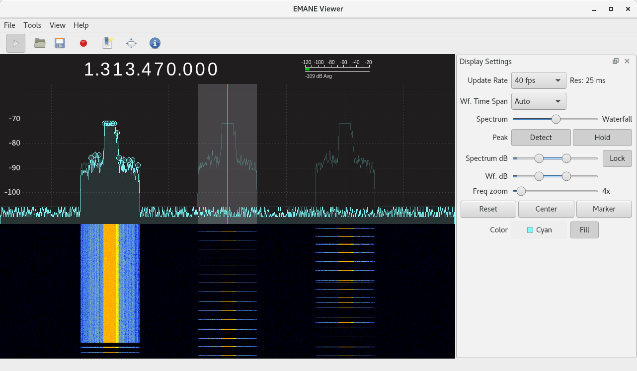
eView Display Components
eView is composed of the following visual components as shown in the following figure:
- The current frequency of interest.
- A signal strength meter showing the average signal level for a marked frequency range.
- The RF spectrum view of detected frequencies and signal power levels.
- The waterfall view displaying the spectrum history.
- A display settings control panel.
- A bookmark panel indicating any user defined frequency bookmarks.
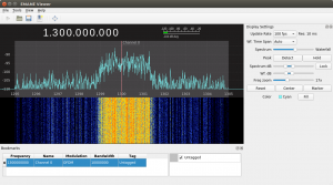
Figure 1: eView Detail View with Frequency Bookmark
eView Display Rate Controls
eView has controls for independently setting the spectral and waterfall view update rates as described in the following paragraphs.
Spectrum View Rate
eView supports data display refresh rates up to 200 frames per second (FPS) providing a data resolution of 5 milliseconds per waterfall view line (when the waterfall display rate is set to “Auto”). Therefore, it is capable of capturing transmissions detected on the EMANE OTA control bus with up to 5 milliseconds of display resolution. When using the 200 FPS display rate, signals whose transmit duration are less than and equal to 5 ms will result in a single line in the waterfall view. The spectral plot display rate ranges from 200 FPS to 1 FPS specifying a spectrum view resolution from a range of 5 ms to 1 sec. The resolution associated with the spectrum view rate is shown on the display options panel upon selecting a spectrum display/sampling rate.
The spectrum view represents the sampling rate for the application. As OTA content is received, it is queued until a display update is required. At that moment, eView checks for all queued OTA frames whose transmit start and end times relative to the current wall clock indicate a transmission is active. For network frames for which the transmission is active relative to the system time, they are used to build the composite spectrum view using data reduction my maximum data value for each displayed frequency.
Waterfall View Rate
The waterfall view time span ranges from the “Auto” setting, to a time value range as 1 minute to 48 hours. The “Auto” setting will update the waterfall plot at the same rate as the display rate set for the spectral plot. For example, when the spectrum view rates is set to 200 FPS, a single line of output to the waterfall view will represent 5 milliseconds of a transmit signal duration. At the 200 FPS spectrum rate, for transmission durations in the EMANE simulation that are less than 5 ms in duration, the signal will be present in only one line of the waterfall view. For the time based setting, the waterfall view will accumulate FFT data carried on EMANE PHY layer network packets over a time range using a maximum value reduction technique (maximum value decimation).
Frequency Band Marker
eView provides a user movable frequency range marker with a predefined bandwidth and center frequency as shown in Figure 1. The frequency marker (grey rectangle) is useful for indicating the marking the bandwidth of a particular signal, which indicates the frequency range for a particular RF modulation. The center frequency of the frequency band marker is the red vertical cursor. The marker can be positioned in the user interface by dragging the marker rectangle using the mouse. The current frequency indicator will display the frequency of the center of the marker corresponding to the red vertical cursor. The width of the marker represents the two side-bands around the center frequency marking the bandwidth of the expected signal.
Other eView Display Controls
Display settings are modified using the Display Settings control panel.
In addition to the two timing controls previously described, eView also includes the following user modifiable and persistent display settings:
- The Spectrum ⇔ Waterfall slider is used to modify the portion of the main display allocated to the spectrum and to the waterfall views.
- The Peak “Detect” button will attach little circles to the spectra peaks of the RF spectrum view.
- The Peak “Hold” buttons will display faintly the envelope of RF spectrum.
- The Spectrum dB slider is used to modify the db Range of the spectrum view. This allows zooming in on a particular range of values.
- The Lock button is used to lock the spectrum and waterfall sliders together.
- The Waterfall dB slider is used to change the colors associated with different spectrum dB levels. This slider can be used to show black or blue colors for noise floor level signals, and white or red for strong level signals. This allows user control of the colors used for the waterfall to match the signal level characteristics of the
- The Freq Zoom slider is used to zoom in on both the Spectrum and Waterfall views to see a particular frequency of interest. This value ranges from 1x (no zoom) up to 50x. Frequency zooming is relative to the center frequency of the spectrum view.
- The Zoom “Reset”, “Center”, “Marker” buttons are respectively for:
- R = resetting the RF spectrum view to its 100% default value
- C = centering the RF spectrum view around the original frequency
- M = centering the RF spectrum view around the user defined marker frequency
- The Color selector changes the color of the RF spectrum view.
- The “Fill” button will fill/clear the space below the spectrum line with a color gradient.
- Zooming and Panning Frequency and Signal Level.
- Zooming in and out of the frequency scale can be performed using either the Frequency Zoom slider, or by click on the frequency scale and using the mouse scroll wheel to zoom in our out. The frequency scale can also be dragged horizontally by use of the mouse.
Signal Strength Indicator
A signal strength indicator is provided that indicates the average signal levels for all signals contained within the frequency marker selector as shown in Figure 1.
Bookmark Frequencies
User defined bookmarks are supporting allowing the user to annotate specified frequencies with labels which appear on the spectrum view as shown in Figure 1.
Display Spreading Mode
A spectrum analyzer displays a signal magnitude at a specific frequency. For a TDMA based communications system, a common shared center frequency is often used.
But what if you desire to view the transmission for a number of EMANE NEMs with some spatial separation, and without the spectrum and waterfall display for each NEM laying right on top of each other on the common center frequency?
To support this test modality, eView provides a configuration option where output for each EMANE NEM occupies a separate vertical display channel when displayed. In this mode, NEM #1 will occupy the leftmost position of the display, and the largest NEM the rightmost.
This display mode is not appropriate for an FDMA based network emulation.
In spread mode, each NEM OTA transmission are shown vertically in an isolated manner to prevent display overlay, both the spectrum waveform as a Power Spectral Density (PSD) plot, and the waterfall plot .
This mode is particularly useful to view NEM transmission history, to view orthogonality and channel access efficiency. This eView option is particular useful when analyzing network routing, where the waterfall view shows the history and frequency of route changes by the network routing software.
View Perspective Modes
eView generally operates with a view perspective that is network centric as “omniscient” mode. In this view mode, signal levels displayed will be scaled based on pathloss information between two communications nodes at global or entire network level/scope. Broadcast and unicast traffic will be displayed using a default pathloss value in this view perspective mode.
When operating using the GPS location based EMANE propagation model, either freespace or 2ray, eView can act as a virtual NEM and can be targeted by the EMANE event subsystem to assign eView a GPS location. This modality allows eView to operate as a “sniffer” node, where eView can be moved to any GPS location in the network topology to provide signal measurements from the assigned location.
For example, Figure 2 shows an EMANE OTA capture for a 30 node network, with unicast continuous network traffic being sent from host #1 to host #30, where NEMs are arranged from the leftmost as NEM #1, to NEM #30 as the rightmost. In Figure 2, eView was positioned 10 meters below NEM #30 for an emulation network of 30 nodes.
To allow for viewing the OTA transmissions from each NEM spatially separately without them laying atop each other on the same center frequency, we utilized an eView option to physically separate each NEM’s OTA activity horizontally to prevent overlaying content as described in the previous paragraph. Each NEM OTA transmission are shown vertically in an isolated manner to prevent display overlay, both the spectrum waveform as a Power Spectral Density (PSD) plot, and the waterfall plot .

Figure 2: eView Display of 30 Node Network from NEM #30’s perspective
Figure 2 shows continuous host-to-host data is being sent from NEM #1 to NEM #30, using multiple hop routing. The waterfall viewer shows a 5 hop route at the bottom of the screen as the oldest routing history, and a 4 hop route as the more recent routing decision. The vertical length of each data column indicates the time duration of the route selection, based on the Update Rate setting in use. For our test configuration of olsrd, route changes are not made more frequently than 5 seconds, so the vertical size of the data column before a route change corresponds to a 5 second duration.
Figure 2 shows as the size of the signal from the perspective of NEM #30, that is the spectrum as NEM #30 views the world. Therefore, the signal level displayed in the spectrum analyzer view and waterfall viewer is the largest for rightmost NEM #30, and decreases to the left of the image as the physical distance increases between a relay node relative to NEM #30.
Signal Capture And Analysis
The majority of real-world signals—from complex modulated communications signals, to interference events, and to pulsed tactical signals—the signal energy can be sporadic, non recurring, or even random. With traditional spectrum analysis, these signals could be nearly impossible to “catch” in an analysis window and trigger on. Present and future communication modulations are increasing the challenge further with techniques, such as frequency hopping, spread spectrum, pulsed, and cognitive radio techniques. Additionally, in order to analyze the quality of these communications, the ability to rapidly process, store, and compare these signals over time is necessary.
eView provides a Start/Stop button to allow the user to start and stop signal acquisition from the EMANE OTA control bus. This allows the user to terminate the display when a particular event has occurred that needs to be captured and analyzed. This feature prevents possible overwrites of the captured signal of interest with new content. The user can then zoom in on a particular frequency of interest for captured signal analysis.
EMANE Common Header Processing
eView utilizes the field values from the EMANE common physical layer header to adjust the received OTA data stream signal power levels for displaying. This includes using the specified transmit center frequency, the transmit path loss, fixed transmit and receiver antenna gains, and transmit power consistent with the receiver processing performed by the EMANE framework.
The EMANE common physical layer header also includes the transmit time relative to the Linux standard epoch (Jan 1 1970), and the transmit duration in microseconds. eView uses this transmit timing information along with the real-time clock on the platform for rendering content to the spectrum and waterfall plots. The content of queue networked packets is rendered if the transmit time start specified is greater than or equal to the platform time and the transmit stop time is not exceeded. Queued network packets are discarded when the transmit stop time is exceeded by the platform time.
Customized Modulation Transmit Power Spectral Density (PSD) Output
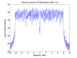 Depending upon the custom or standard communications modulation (e.g. OFDM) and waveform used with a communications system, an RF communications system will have a modulation transmit power spectral density (PSD) frequency distribution, or curve, around a center frequency that spans a certain bandwidth. For example, an amplitude modulated (AM) signal consists of a carrier with two side-bands that extend out from the main carrier. When using narrow-band FM, and FM signal consists of the carrier and the two sidebands spaced at the modulation frequency on either side of the carrier, similar to an AM signal, but the difference is that the lower side-band is out of phase by 180 degrees. OFDM, which has been adopted for wireless standards such as IEEE 802.11a, uses the sum of several sinusoidal channels, and has a PSD curve similar to the reference figure.
The PSD output for the modulation being modeled describes how power of a transmission signal or time series is distributed over a frequency range centered around the center frequency of the transmission. As shown in the referenced figure, the PSD signal frequency distribution in the spectrum and waterfall views is for OFDM modulation with a 10 MHz bandwidth (5 MHz on each side of the center frequency).
EMANE specifies the characteristics of a transmission such as wall clock time of transmit, transmit power, transmit and receive antenna gains, and one or more frequency segments that make up a transmission. eView builds upon these EMANE transmit attributes by leveraging the functionality of a custom EMANE Physical Layer (PHY) shim, which adds higher fidelity to RF physical layer characteristics by including spectral power levels for the full frequency range of the modulation. For OFDM modulation, this includes 1024 FFT data points for a 10 MHz signal bandwidth.
eView utilizes a custom EMANE shim that is part of the EMANE NEM stack that provides a bandwidth specific custom modulation PSD spectra power level distribution for a transmission that is broadcast along with the EMANE OTA network frame. This custom shim transparently adds and removes the custom PSD content below the EMANE PHY layer so that the EMANE emulation stack operates nominally without any knowledge of the customization and added content. Custom modulation PSD signatures can be used by making changes to this custom EMANE shim. By using the features of this custom EMANE PHY layer shim, spectral waveforms displayed have familiar patterns to what occurs with actual RF over-the-air transmissions.
PSD Display Scaling
For each received packet, eView computes the receiver power associated with that packet using the following calculation (as does the EMANE framework):
rxPower = txPower + txAntennaGain + rxAntennaGain − pathloss
The rxPower level is numerically subtracted from each value in the provided PSD waveform image to scale the displayed waveform based on receive power.
The systemnoisefigure EMANE setting is used to add random noise values to the displayed PSD waveform to represent system noise visually.
pathloss is the pathloss between transmitter and receiver determined based on the EMANE propagationmodel configuration parameter. It is calculated in the custom eView PHY Layer shim and provided to eView as part of the interface messaging.
EMANE OTA Signal Capture Persistent Storage and Analysis
It is often important to capture as test artifacts the sequence of transmit messages generated during an EMANE emulation session. These captures can be used to record the behavior of a emulation under a certain test condition, for comparison to other captures under different test conditions, or at a different development time for regression testing.
eView provides support for recording and saving the detailed information for OTA packets that is displays in the spectrum and waterfall views during an EMANE emulation session (excluding the PSD values). It does so using the embedded visualization technology described as Embedded Visualizer. Test information is persistently stored in Verilog Value Change Dump (VCD) file format per RFC IEEE Standard 1364-2001. This is shown in the following representative screen capture which is a gtkwave display of an eView VCD capture from a network of 3 radios.

Figure 3: eView VCD Signal Capture and Display
Information stored in the value change dump file includes the attributes provided to eView from the custom eView PHY shim in the EMANE NEM stack (excluding the PSD values), which includes important information from the EMANE Common PHY Header used to scale the PSD values provided for display:
- bandWidth is the EMANE transmit bandwidth in KHz.
- destId is the EMANE NEM destination id of the transmission (65,535 for broadcast destination).
- frequencyKHz is the transmit center frequency in KHz.
- pathloss is the pathloss calculated by the eView PHY shim between the transmitter and receiver determined based on the EMANE propagationmodel configuration parameter.
- rxAntennaGain is the fixed EMANE receive antenna gain in dBi (assumed to be uniform of all NEMs).
- sequence is a unique atomically increasing sequence number from the EMANE Common PHY Header.
- sourceId is the EMANE NEM source id of the transmission.
- systemNoiseFigure is the EMANE configuration parameter systemnoisefigure in dB.
- txAntennaGain is the EMANE transmitter antenna gain in dBi.
- txPower is the EMANE transmit power via the Common PHY Header in dBm, which can be different for each transmission.
- txOn is the transmitter ON duration represented as a time duration signal starting with the transmit start to transmit end time.
- dscp is the Differentiated Services Code Point of the packet, which is typically used to implement Quality of Service (QoS) policies.
- packetSize is the size or length in bytes of the packet.
All of the captured signals are defined as numeric values when displayed in gtkwave, the exception being the txOn signal which is represented as a time duration beginning with the transmit start time and ending after the transmit duration. The txOn signal can be used to visualize transmit orthogonality as required for half duplex communications links.
VCD signal captures are organized by radio in the gtkwave left frame marked Signal Search Tree (SST). Figure 2 shows detailed information for NEM#1 (source id of 1), showing only olsrd network routing traffic to the broadcast destination at 0.5 second intervals for a network of three radios. Detailed signals displayed for radio 1 include:
- 10 MHz signal bandwidth.
- 1.28 GHz center frequency.
- A fixed system noise figure of 4 dB.
- A fixed tx antenna and rx antenna gain with values of 0 dBi.
- A tx power of 0 dBm.
- An 80 dB path-loss.
The txOn signals for the 3 radios (labelled R01_TxON, R02_TxON, R03_TxON) are displayed at the bottom of Figure 2 concurrently to examine transmit orthogonality, transmit durations, and analyze RF channel utilization efficiency for a time-division multiple access (TDMA) based communications system.
Distributed Deployment
eView is typically executed on the same platform as the EMANE network emulation as time synchronization is required between them. Similar to the available EMANE environment modes, this is described as a centralized deployment. eView can also be used on a separate physical platform from the EMANE network emulation in a distributed deployment.
Distributed deployment requires the use of the EMANE transport mechanism as described in the EMANE documentation, as well as ensuring that the two platforms are in time synchronization. High accuracy time synchronization between platforms is usually implemented using the Precision Time Protocol (PTPv2) to achieves clock accuracy in the sub-microsecond range. eView was developed to operate on various operating systems using the cross platform Qt application framework.
Conclusion
EMANE is an industry leading network emulation framework for real-time design and analysis of networking systems. The eView application supplements this open source framework by providing real-time graphical display and captures to help in the analysis of network emulation results. While eView currently supports real-time data collection directly from the EMANE over-the-air (OTA) control bus, it may also be driven (with some customization) with stream results from other applications which benefit from real-time spectrum and waterfall views.
eView extends EMANE’s capabilities to provide advanced features for visualization and analysis of RF spectrum data using a spectrogram in real-time. eView supports viewing and inspection of the frequency spectrum during real-time network emulation of collected OTA data.
The eView waterfall view continuously displays signal strength history during EMANE network emulation of a user selectable frequency range using a user defined intuitive color scale that is customized to the signal level range of the signals of interest.
The eView VCD capture functionality allows for persistent storage of emulation generated OTA transmit frames, and for detailed timing analysis.
Additional capabilities include:
- narrowing the span of the frequency range to focus on a signal
- frequency bookmarks
- signal peak and hold display in the spectrum view
- frequency range marking
- waterfall display export to an image file